After implementing BSSRDF importance sampling for Normalized Diffusion and GGX BRDF, I started wondering how realistic could the appearance of human skin be achieved with the combination of these two models. The whole development process is quite interesting, because it’s a perfect combination of my two interests: programming and photography. With only one diffusion layer and two specular layers on top, I tried to find the way to make it as realistic as possible.
Visual Components of Realistic Human Skin
Before even write any code, we need to know the key ingredients of the realistic human skin at first. Based on “The Appearance of Human Skin” by Takanori Igarashi et al. [1], the visual details observed by naked eye could be classified as:
- soft color diffusion from skin layers (i.e. epidermis, dermis and subcutis)
- glossy reflection caused by skin surface lipids
- fine wrinkles and hair
- wrinkles, creases, pores, freckles, spots
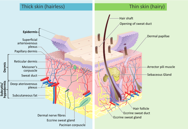
While the common layout of skin shader is modeled as (from top to bottom):
- skin surface lipids (thin oily layer)
- epidermis
- dermis
- subcutis
In this framework, the epidermis, dermis and subcutis are often referred to as shallow, mid and deep scattering. Among different renderers, the scattering layer is modeled by BSSRDF with various diffusion profile: Quantized-Diffusion (Weta), Cubic/Gaussian (Arnold, Cycles), Normalized Diffusion (RenderMan, Disney), and so on.
Other diffuse details, like wrinkles, pores, freckles, could be handled by regular approaches with color texture and normal/bump/displacement mapping.
The thin oily layer on top is an interesting one, its specular reflection is commonly modeled by physically based microfacet BRDF [2, 3, 4, 5] and it is sometimes decomposed into sheen and specular components in recent skin shader implementations. Now, the curious thing is why do we need two specular components to represent realistic reflection?
To my best knowledge, two specular lobes might come from the astonishing work done by Graham et al. [2]. They found the specular reflection from their measured data could be approximated well by two lobes of a Beckmann distribution instead of one. And this principle is also adopted in another amazing real time domo by von der Pahlen et al. [3].
Layer Combination
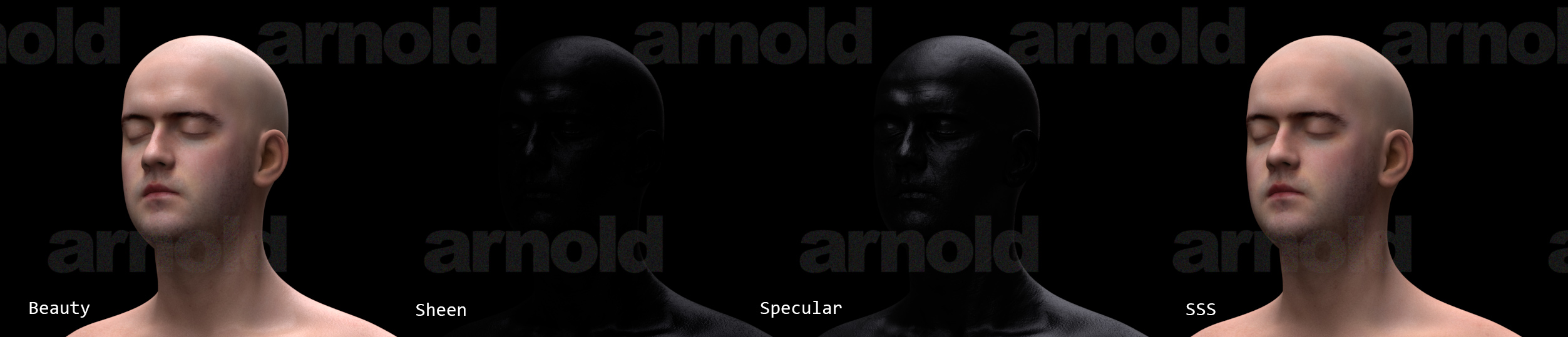
In my skin shading experiment, two specular lobes are modeled with GGX BRDF with different roughness, while the sub-surface scattering is computed with the Normalized Diffusion profile. For the combination of these shading layers, the naïve way is simply to accumulate each shading result, but this would look a little glow near the silhouettes [4]. The other way is to use the out-scattering Fresnel terms of given viewing direction to weight each layers, but this would make the silhouettes too dark [6].
Another more accurate way is to compute the weight for SSS layer with the energy which is not reflected from top oily layer [2, 4, 5]. In other words, it uses one minus the average hemispherical diffuse reflectance as weights for linear interpolation:
where \(f_r(x,\vec{\omega_o},\vec{\omega_i})\) is the microfacet BRDF
Although the average diffuse reflectance could be done at pre-processing stage (e.g. the node_initialize section), yet it would still affect the user experience of parameter tweaking in IPR mode. And just inspired by alSurface [6], I extract \(F_t(\eta, \vec{\omega_i})\) out from the BSSRDF:
$$S_d(x_i,\vec{\omega_i};x_o,\vec{\omega_o})=\frac{1}{\pi}F_t(\eta,\vec{\omega_i})R_d(\vert x_i-x_o\vert)F_t(\eta,\vec{\omega_o})$$
and compute its average from GGX BRDF as blending weights:
$$\text{sssWeight} = 1 - \text{specularAvgFresnel} \times (1 - \text{sheenAvgFresnel})$$
With such layer combination, the visual difference between one and two glossy lobes is:
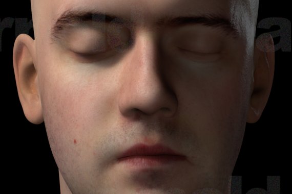
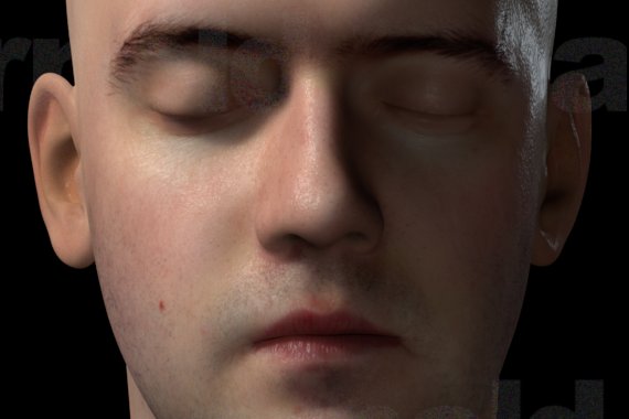
and the influence of avgFresnel weighting is near the silhouette of cheek and nose:

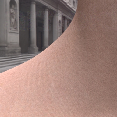
Microstructure Details
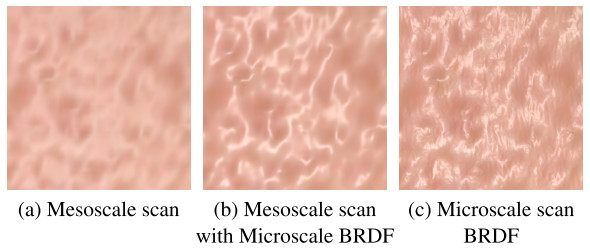
As mentioned by Graham et al. [2], current face scanning techniques only provide mesostructure details like wrinkles, pores and creases. Hence they proposed a texture synthesis method to compute the high-resolution texture of microstructure bumps for more realistic reflection in close-ups.
In contrast, instead of using high-res synthesized texture, Jimenez and von der Pahlen [3] has demonstrated that the microstructure can be approximated with simple sinusoidal noise in real time context.
Since the storage of the microstructure texture is quite large, the micro-displacement map from Digital Emily 2 is about 298MB (and its tx file consumes 1.1GB!). Thus, I tried to follow the concept of second approach to blend a solid fractal noise with bump map texture to break the specular highlight:

Fading Out Diffusion by Surface Cavities
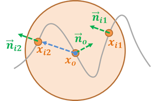
The formula in my previous implementation was incorrect for back-facing diffusion. I’ve tweaked the formula a little bit, for back-facing diffusion, I use \(\cos{\theta}\) as the weight for fadeout instead of \(\cos{\theta/2}\). Where the \(\theta\) is computed as:
With the consideration of surface cavities, it would reduce the diffusion amount from the opposite faces at front:
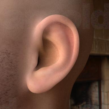

Results
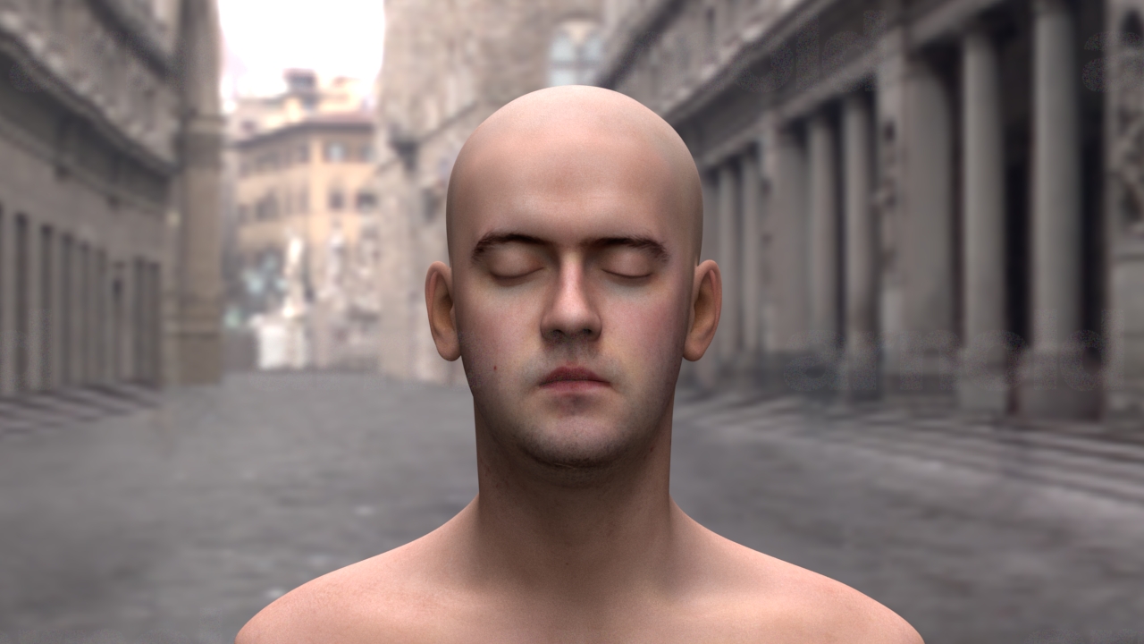
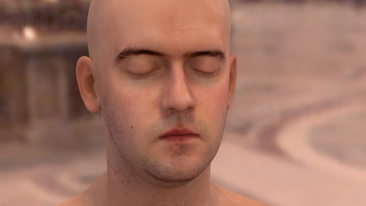
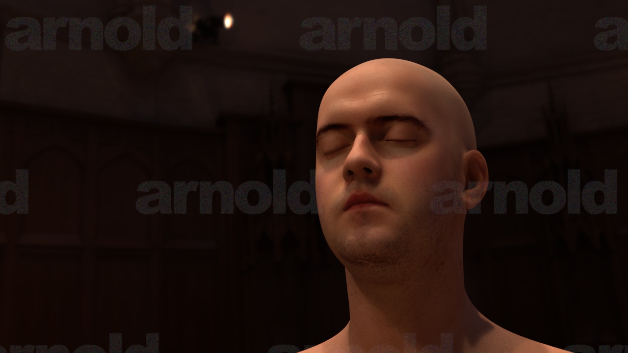
As usual, the source code could be found here.
Graphics data sources:
- Model/textures: Infinite Realistic Head Scan
- Light probes: High-Resolution Light Probe Image Gallery from USC ICT
Limitations of My Current Implementation
If the scatter distance is smaller than the edge length of hit triangle, the probe samples along U, V axis would totally lost, which would cause following artifact:
I’ve tried to increase the probability of the probing along normal direction for this case, but it still can’t eliminate such artifact completely. Because at the surface point with low geometry curvature within a range of max scattering radius, it would still potentially waste most samples along U, V axis.
The other thing is about the scattering distance control. The normalized diffusion is integrated to one for any positive distance \(d\), and current implementation distributes energy of each color channel among the given scatterDist components respectively.
The scattering energy is decayed from hit point, due to normalization, the farther distance it scatters the less energy it contributes near the hit point. In other words, to get more reddish results, we need to make the scatterDist.r relatively smaller than scatterDist.g and scatterDist.b. This might be a little counterintuitive to users. (This is a problem of my current implementation, not related to the normalized diffusion model itself. It seems that the parameters used in the course note [7] don’t have such problem)
The last thing is about energy conservation of layer combination, the layer blending so far is an ad-hoc solution. The new layer framework proposed by Jakob et al. [8] is an interesting direction for further studying. Besides, my GGX BRDF implementation would lost energy with high roughness values, this might be resolved with a new technique from Heitz et al. [9] which handles the multiple-scattering case within microfacet model.
References
- Igarashi, Takanori, Ko Nishino, and Shree K. Nayar. “The appearance of human skin: A survey.” Technical Report. 2005.
- Graham, Paul, et al. “Measurement‐Based Synthesis of Facial Microgeometry.” Eurographics. 2013.
- Jimenez, Jorge. and Javier von der Pahlen. “Next Generation Character Rendering” [demo]. GDC'13.
- d’Eon, Eugene, and David Luebke. “Advanced Techniques for Realistic Real-Time Skin Rendering”. GPU Gems 3 Ch. 14. 2007.
- Donner, Craig, and Henrik Wann Jensen. “Light diffusion in multi-layered translucent materials.” SIGGRAPH. 2005.
- Langlands, Anders. “Physically Based Shader Design in Arnold.” SIGGRAPH Course Notes. 2014
- Burley, Brent. “Extending the Disney BRDF to a BSDF with Integrated Subsurface Scattering.” SIGGRAPH Course Notes, 2015.
- Jakob, Wenzel. “layerlab: A computational toolbox for layered materials.” SIGGRAPH Course Notes, 2015.
- Heitz, Eric, Johannes Hanika, Eugene d’Eon, and Carsten Dachsbacher. “Multiple-Scattering Microfacet BSDFs with the Smith Model.” Technical Report. 2015.
comments powered by Disqus